Multiwfn forum
Multiwfn official website: http://sobereva.com/multiwfn. Multiwfn forum in Chinese: http://bbs.keinsci.com/wfn
You are not logged in.
- Topics: Active | Unanswered
#1 2020-10-27 09:05:27
- Mvr2301
- Member
- Registered: 2020-10-18
- Posts: 4
How do we calculate the local excitation and charge transfer ?
How does the software gives us the percentage of the local excitation and charge transfer of each excited state present in the system? Will it provide me any details of the RISC(from A-D) and RIC(From A-A) of a donor and acceptor molecule which will be helpful for OLED molecules? Why I am mentioning RISC and RIC is because I consider that RISC corresponds to the Charge transfer state and RIC refers to Local Excitation. What does the question mark indicates in the following attachment?

Offline
#2 2020-10-27 09:25:29

Re: How do we calculate the local excitation and charge transfer ?
The percentage of CT character can be characterized in many ways by Multiwfn, for example, see this part of Section 4.18.1 of Multiwfn manual on how to quantify it according to the data given by hole-electron analysis:
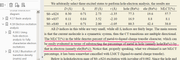
Note that the value of CT% is closely related to the definition of fragments. The acceptor and donor may be defined as the fragments in the analysis.
In addition, you can use the IFCT (interfragment charge transfer) analysis to obtain various details of charge transfer between fragments, see Section 4.18.8 of manual for examples.
In the table you mentioned, the question mark denotes that the magnitude of the corresponding quantity is not clear, it may be small and may be large, depending on practical situation.
Offline
#3 2020-10-27 12:10:24
- Mvr2301
- Member
- Registered: 2020-10-18
- Posts: 4
Re: How do we calculate the local excitation and charge transfer ?
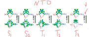
Thank you. The provided explanation cleared my doubts. I am working with Organic LEDs, mostly I will deal with organic molecular fragments like a Donor and Acceptor. I will try to explain with the following attachment, there are two local excitations(Donor and Acceptor) that can occur in the same molecule and a charge-transfer state. Could we really differentiate between those two local excitations?
Now there is one new topic that has been exploring in my field is "Reverse Intersystem Crossing (RISC) and Reverse Internal Conversion(RIC)". Is there any parameter that can calculate those results in the software?

Last edited by Mvr2301 (2020-10-27 12:19:37)
Offline
#4 2020-10-28 00:28:59
Re: How do we calculate the local excitation and charge transfer ?
Sure, both hole-electron analysis and IFCT analysis are able to clearly differentiate CT states from LE states. For example, in the hole-electron analysis module, after calculating grid data, you can display both hole and electron distributions, if the hole and electron are respectively distributed on donor and acceptor moieties, you can conclude that this excitation is a typical CT excitation. In contrast, if the overlap between hole and electron is remarkable and they locate both on acceptor moiety, this excitation is obviously a local excitation of the acceptor fragment.
If you want to calculating RISC and RIC rates, it is a quite difficult topic. The simplest quantity that can qualitatively measure the feasibility of the two processes is adiabatic gap between the corresponding two states. If the gap is low enough, the RIC and RISC should be possible. For RISC, you also need to take spin-orbit coupling into account, which strongly influences ISC/RISC rate.
Offline
#5 2021-10-21 04:19:45
- Usman Ali
- Member
- Registered: 2021-10-13
- Posts: 13
Re: How do we calculate the local excitation and charge transfer ?
The percentage of CT character can be characterized in many ways by Multiwfn, for example, see this part of Section 4.18.1 of Multiwfn manual on how to quantify it according to the data given by hole-electron analysis:
https://i.postimg.cc/PPnfdFJ5/Clipboard01.png
Note that the value of CT% is closely related to the definition of fragments. The acceptor and donor may be defined as the fragments in the analysis.
In addition, you can use the IFCT (interfragment charge transfer) analysis to obtain various details of charge transfer between fragments, see Section 4.18.8 of manual for examples.
In the table you mentioned, the question mark denotes that the magnitude of the corresponding quantity is not clear, it may be small and may be large, depending on practical situation.

I have read you response on this post which is likely of my interest. I have some confusions and questions regarding CT and LE percentage calculations. My first question is as you mentioned the table in MLCT % values are given, So I want to know how I can get this table as there is no output results during using the IFCT module of Multiwfn?
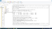
My second question is what will be the next step during using the IFCT module for calcuting CT and LE% in Multiwfn as I also attached the screenshot of my querry.
My third confusion is as you used MLCT and LMCT term for your response also in manual and also in reply of this post, so in our case as we are working on OLEDs then we will use the same term for calculating the CT and LE % ?
My last confusion is as you mentioned hole (Ru%), ele (Ru%) and MLCT (%) for explanation but it creates a confusion for beginers that what is simply the CT% and what will be the LE% for our calculations?
Although, I asked four questions at the same time but I hope you should respond me in details. I am very hopeful on having this forum for clearing my confusions and to complete the analysis.
Your response should be highly respected.
Thanks
Offline
#6 2021-10-21 22:10:55
Re: How do we calculate the local excitation and charge transfer ?
Although, I asked four questions at the same time but I hope you should respond me in details. I am very hopeful on having this forum for clearing my confusions and to complete the analysis.
Your response should be highly respected.
Thanks
1 If you partition the whole system as two fragments in IFCT analysis, assume that sum of charge transfer of 1->2 and 2->1 is e.g. 0.8, that means %CT is 80%.
2 You should always follow the prompt on screen, the prompt in each step is very clear. I strongly suggest you to reproduce the IFCT analysis in Section 4.18.8 of Multiwfn manual, you will learn the usage and basic idea of IFCT analysis.
3 MLCT and LMCT are only defined for transition metal coordinates. For other kinds of systems these words are inappropriate. For OLED, there is no transition metal atom and ligands at all.
4 I believe there is no evident confusion.The meaning of hole and electron has already been clearly described in Section 3.21.1, and MLCT is a well recognized concept, you can find abundant introductory materials via Google. MLCT(%) simply refers to CT(%) from metal (M) to ligands (L) during a specific electronic excitation.
Offline
#7 2021-10-25 04:25:09
- Usman Ali
- Member
- Registered: 2021-10-13
- Posts: 13
Re: How do we calculate the local excitation and charge transfer ?
Usman Ali wrote:Although, I asked four questions at the same time but I hope you should respond me in details. I am very hopeful on having this forum for clearing my confusions and to complete the analysis.
Your response should be highly respected.
Thanks
1 If you partition the whole system as two fragments in IFCT analysis, assume that sum of charge transfer of 1->2 and 2->1 is e.g. 0.8, that means %CT is 80%.
2 You should always follow the prompt on screen, the prompt in each step is very clear. I strongly suggest you to reproduce the IFCT analysis in Section 4.18.8 of Multiwfn manual, you will learn the usage and basic idea of IFCT analysis.
3 MLCT and LMCT are only defined for transition metal coordinates. For other kinds of systems these words are inappropriate. For OLED, there is no transition metal atom and ligands at all.
4 I believe there is no evident confusion.The meaning of hole and electron has already been clearly described in Section 3.21.1, and MLCT is a well recognized concept, you can find abundant introductory materials via Google. MLCT(%) simply refers to CT(%) from metal (M) to ligands (L) during a specific electronic excitation.
Thank you for your answer. I have cleared my concept about %CT and %LE chracters calculations via IFCT method. Although it is great tool for analysis. I have question about IFCT calculations at different excited excited states as I have performed the Adiabatic calculations for different excited states like S1, S2, T1, T2 and T3 for OLEDs molecules. During the IFCT calculations for % CT and % LE, the excited states on the screen is always as Exc. 1, Exc. 2 and Exc. 3. As in the case of S1 TDDFT calculations, I select the Exc. 1 state for % CT and % LE results but in the case of S2, I have selected the Exc. 2 for %CT and %LE charcters but the results are huge different from S1 and S2 %CT and %LE charcters although the pictures of HOMO and LUMO at both excited state are nearly same not a much different. So, my question is that how we can perfomed the IFCT analysis for calculating the % CT and % LE charcters for different excited states?
Either for S1, we need to pick the Exc. 1 and S2, we need to pick the Exc. 2 results and so on?
Either in all case we will select the Exc. 1 does not matter which file we load for IFCT analysis as S1, S2, T1, T2 and T3 etc because if I pick the Exc.1 in different geometries analysis like S1, S2, T1, T2 and T3 then the results are nearly same and looking acceptable when we compare these results based on their molecular HOMO and LUMO orbitals pictures. I have also attached the screens shots of my questions. I have completely share the results for your clear understanding about my querries.
Kindly respond me in this regard.
Offline
#8 2021-10-25 05:13:56
Re: How do we calculate the local excitation and charge transfer ?
You statement is a bit too complicated and somewhat confused me. I would like to clarify a few key points:
(1)TDDFT calculation is performed based on ground state wavefunction, which is known as reference state. For a specific geometric structure, the S1, S2, T1, T2 ... excited states calculated by TDDFT are represented based on the same set of orbitals, namely ground state MOs, but their configuration coefficients are different. Assume that ground state electronic state is S0, then in IFCT analysis, if in the current case Exc. 2 corresponds to S2 and you selected it, then IFCT analysis will be performed for S0-S2 excitation.
(2)At different geometries, the ground state MOs are different. Hence, if you optimized S0, S1, S2 states... respectively, you will find the MOs recorded in the .fch files generated by these calculations are different. If two geometries differ with each other marginally, then their MOs should have very similar characters.
(3)IFCT can only be used to characterize vertical transition, it cannot be used for studying adiabatic transition. For example, you can use IFCT to analyze S0-S1 transition at S0 geometry, and you can also analyze S0-S1 excitation at S1 or other geometies, this depends on your practical purpose. For example, if you are interested in vertical absorption from S0 to S2 state at geometry of ground state S0, you should perform TDDFT calcluation at optimized S0 geometry, then in the IFCT analysis select "Exc. 2". Another example, if you want to characterize S1-S0 vertical emission at S1 geometry, you should optimized S1 first, then select "Exc. 1" in the IFCT analysis interface.
Using HOMO and LUMO to discuss transition character is highly deprecated. Since it is very rare that an electron excitation is fully dominated by HOMO-LUMO transition. Sometimes, even the lowest electron excitation may solely contributed to transition between other MOs, for example I found S0-S1 excitation of azobenzene at TD-PBE0/6-31G* level almost completely corresponds to HOMO-1 to LUMO transition.
Offline
#9 2021-10-25 06:26:11
- Usman Ali
- Member
- Registered: 2021-10-13
- Posts: 13
Re: How do we calculate the local excitation and charge transfer ?
You statement is a bit too complicated and somewhat confused me. I would like to clarify a few key points:
(1)TDDFT calculation is performed based on ground state wavefunction, which is known as reference state. For a specific geometric structure, the S1, S2, T1, T2 ... excited states calculated by TDDFT are represented based on the same set of orbitals, namely ground state MOs, but their configuration coefficients are different. Assume that ground state electronic state is S0, then in IFCT analysis, if in the current case Exc. 2 corresponds to S2 and you selected it, then IFCT analysis will be performed for S0-S2 excitation.
(2)At different geometries, the ground state MOs are different. Hence, if you optimized S0, S1, S2 states... respectively, you will find the MOs recorded in the .fch files generated by these calculations are different. If two geometries differ with each other marginally, then their MOs should have very similar characters.
(3)IFCT can only be used to characterize vertical transition, it cannot be used for studying adiabatic transition. For example, you can use IFCT to analyze S0-S1 transition at S0 geometry, and you can also analyze S0-S1 excitation at S1 or other geometies, this depends on your practical purpose. For example, if you are interested in vertical absorption from S0 to S2 state at geometry of ground state S0, you should perform TDDFT calcluation at optimized S0 geometry, then in the IFCT analysis select "Exc. 2". Another example, if you want to characterize S1-S0 vertical emission at S1 geometry, you should optimized S1 first, then select "Exc. 1" in the IFCT analysis interface.
Using HOMO and LUMO to discuss transition character is highly deprecated. Since it is very rare that an electron excitation is fully dominated by HOMO-LUMO transition. Sometimes, even the lowest electron excitation may solely contributed to transition between other MOs, for example I found S0-S1 excitation of azobenzene at TD-PBE0/6-31G* level almost completely corresponds to HOMO-1 to LUMO transition.

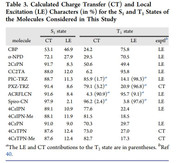
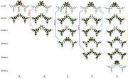
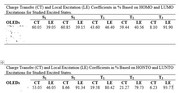
Thank you for your response. I would like to clear my statement as I have optimized the different geometries like S0, S1, S2, T1, T2 and T3. After optimizing these different geometries, I have calculated their TDDFT with TDA-wb97xd/6-31g(d,p) keywords calculations for excited energy and for configuration coefficients. I have also calculated their NTOs with TDA keywords. I want to calculate the % CT and % LE for each excited state. I have also attached the one reference paper images for your understanding in which % CT and % LE have been calculated at different excited states. I have performed both vertical (optimized S0 geometry and then use this geometry as a reference to calculate the TDDFT calculations for S1, S2, T1, T2 and T3) and adiabatic (Optimized the S1, S2, T1, T2 and T3 excited states and then used S1 optimized geometry for calculations of S1 excited state TDDFT calculations and similarly S2 optimized geometry used for S2 TDDFT Calculations, T1 optimized geometry used for T1 TDDFT calculations ........etc) calculations. This was the confusion which I am facing during % CT and % LE charcters calculations during IFCT analysis because I am just finding there only three excited states and I am confused that either in every case I will use Excited State 1 aur different but you have make it clear that excited state 2 means S0->S2. I should repeat my question as I want to calculate the % CT and % LE at different excited states and I have the optimized geometries and their TDDFT calculations with vertical and adiabatic geometries. I hope now my question is clear and you can guide me in easiest way.
The most important point as you mentioned in (3) of your answer as if I want to calculate the S1->S0, then first I need to optimized the S1 geometry and then perform the TDDFT calculations. So, its means to calculate the % CT and % LE at this state I will use the .fchk file of TDDFT calculations based on S1 optimized geometry?
Secondly, If I will use the T3 optimzed geometry and perform the TDDFT calculations, so its means it will give me emission energy of T3->S0 then I want to calculate the % CT and % LE at this state T3 and my question is that in IFCT analysis I will select the Excited state 3?
Thank you soo much for your attentions and your time.
Last edited by Usman Ali (2021-10-25 06:36:11)
Offline
#10 2021-10-26 05:26:41
Re: How do we calculate the local excitation and charge transfer ?
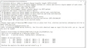
I am just finding there only three excited states
How may excited states can be found from screen depends on how many excited states were calculated by TDDFT task. For instance, in the "examples\excit\4-nitroaniline.out" involved in the IFCT example in Section 4.18.8 of Multiwfn manual, the keyword for calculation is "# PBE1PBE/6-311G* TD IOp(9/40=4)". Since "nstates" option in "TD" keyword was not explicitly specified, the "nstates" is default to 3 (the lowest three excited states are calculated), hence you can find excited states 1, 2 and 3 in IFCT interface. Since all calculated excited states are singlet by default in this case, the three excited states correspond to S1, S2, and S3 respectively. Clearly, if you select e.g. Exc. 2, then S0-S2 transition at current geometry will be analyzed by IFCT method; if you select e.g. Exc. 1, then S0-S1 transition at current geometry will be analyzed, etc.
The most important point as you mentioned in (3) of your answer as if I want to calculate the S1->S0, then first I need to optimized the S1 geometry and then perform the TDDFT calculations. So, its means to calculate the % CT and % LE at this state I will use the .fchk file of TDDFT calculations based on S1 optimized geometry?
Correct. Then if you load corresponding .out file and select Exc. 1 in IFCT analysis interface, then S0-S1 transition at the S1 minimum geometry will be analyzed, the result can be used to derive %CT and %LE and characterizes the S1->S0 vertical (fluorescence) emission process.
Secondly, If I will use the T3 optimzed geometry and perform the TDDFT calculations, so its means it will give me emission energy of T3->S0 then I want to calculate the % CT and % LE at this state T3 and my question is that in IFCT analysis I will select the Excited state 3?
This depends on your keyword for TDDFT calculation. For example, if you use "TD(triplet)", then all the calculated excited states (by default, three excited states) will be triplet, and in this case, the Exc. 1, 2, 3 in IFCT analysis interface will correspond to T1, T2, T3. So, if you select Exc. 3 in this case, transition of S0-T3 at optimized T3 geometry will be analyzed by IFCT method. Since the current geometry is T3 minimum structure, the result can be used to characterize vertical (phosphorescence) emission of T3->S0.
Offline
#11 2021-10-26 05:59:06
- Usman Ali
- Member
- Registered: 2021-10-13
- Posts: 13
Re: How do we calculate the local excitation and charge transfer ?
Thank you very much. After a detailed questions my all the questions have been cleared and I have learned alot from your detailed answers. I can say this forum is really a great opportunity for all of us Multiwfn users. I have asked you many questions and you have responded all the answers in very humble way. Thank you soo much.
Offline